Components of Structured Cabling
📚 Standardization Overview
- Structured Cabling Standards = A uniform cabling system followed by every organization, regardless of vendor.
- Main Authority:
- Previously: EIA/TIA
- Now: ANSI/TIA
- Common notation: ANSI/TIA-568
Note: EIA was the old body; now ANSI accredits these standards. The names have changed, but the standards remain the same.
🧱 Purpose of Structured Cabling
- Standardization: To optimize installation and performance.
- Applicable to:
- Any media (fiber, copper, etc.)
- Any transmission technology
- Any network speed
Reflection: As systems grow, standardization ensures consistency and low maintenance.
🏗️ Key Design Principle
- Hierarchical Design
- Assumes: Star topology in network layout
- Each node connects through a switch—centralized control.
Personal Note: This design makes the network scalable, manageable, and fault-tolerant. A very smart architecture.
📅 Versioning & Updates
- Current Major Version:
ANSI/TIA-568-D- Published: 2015–2017
- Updated every few years to incorporate new technologies.
📌 Takeaway
Why I Still Use Structured Cabling Concepts:
- To build scalable networks
- To ensure predictable performance
- To maintain vendor independence
🛠️ From Demarc to Workstation (Network Layout Flow)
🔌 1. Demarc (Demarcation Point)
- Definition: Where the ISP’s (Internet Service Provider) responsibility ends and the organization’s begins.
- Usually Located:
- In the building’s basement or a secure telecom room.
- Key Device: Smart jack or CPE (Customer Premises Equipment).
Reflection: Monitoring the demarc point is crucial because this is where the incoming line arrives.
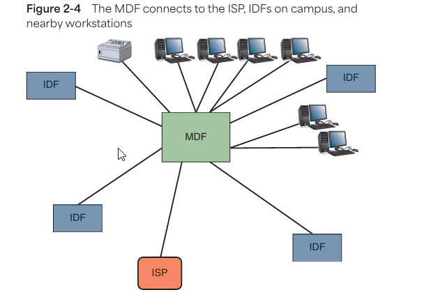
🏢 2. MDF (Main Distribution Frame)
- Purpose: Acts as the central hub of the campus—all IDFs connect here.
- Located in: Main building or data center.
- Contains:
- Core switch
- Routers
- Firewalls
- Patch panels
- Backbone cabling (fiber/copper).
Personal Insight: If the MDF setup is correct, the entire network remains stable and fast.
🏬 3. IDF (Intermediate Distribution Frame)
- Role: Local distribution point for a floor or specific building section.
- Connected To: MDF via backbone cabling.
- Contains:
- Floor switches
- Patch panels
- Cross-connects.
Reflection: IDFs are strategically placed—this keeps cable runs short and maintenance easy.
🪑 4. Workstation Area
- End Point Devices:
- Computers, IP phones, printers, etc.
- Connection via:
- Horizontal cabling from IDF (usually Cat 6 or Cat 6A).
- Typically Includes:
- Wall jack → Patch cable → Device.
Note to Self: Numbering and documentation for each workstation are essential for troubleshooting.
🗺️ 📊 Diagrams (Figure 2-1 & 2-2)
Since the diagrams aren’t here, but to understand:
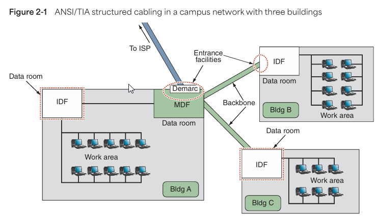
- Figure 2-1: Top-down layout—Demarc → MDF → IDF → Workstations.
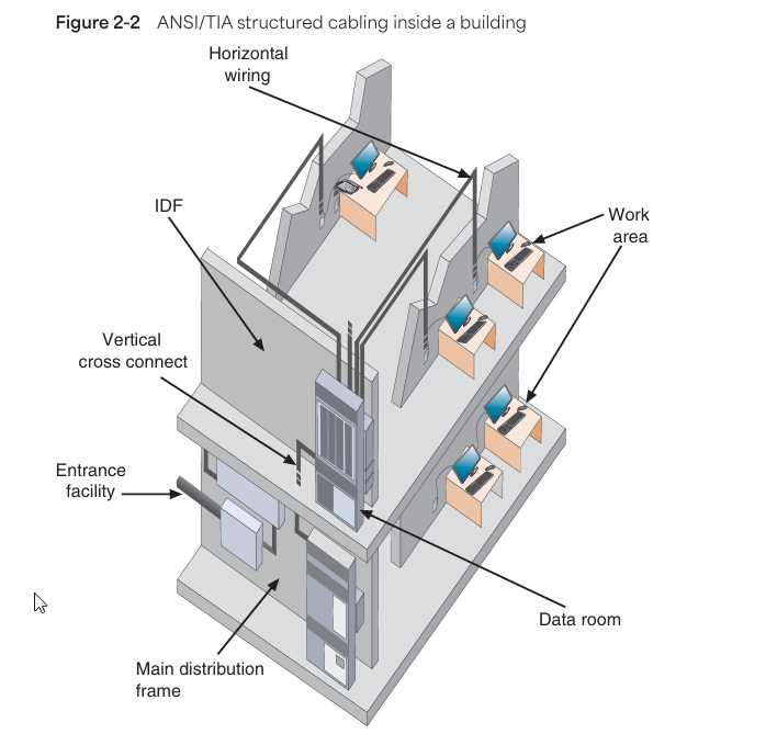
- Figure 2-2: Side view (cross-section) of building infrastructure—floors, cable paths, equipment rooms.
✅ Summary Flow:
Demarc → MDF → IDF → Workstation
Reflection: Once I understood this flow, troubleshooting and planning became easier. It creates a visual and logical map in every technician’s mind.
🏁 Tour Stop 1: Building A’s Entrance Facility
🔑 EF (Entrance Facility)
- Definition: Where the external network (WAN/MAN) connects to the internal network (LAN/CAN).
- Includes:
- Incoming cabling from ISP (fiber, coax, etc.).
- Protective equipment (lightning arrestors, grounding, surge protection).
- Service provider’s gear (smart jacks, NID, transceivers).
- Use Cases:
- Large buildings: A full equipment room or data closet.
- Small buildings: Wall-mounted boxes or enclosures at cable entry.
Note: The EF can also serve as an entry point for other campus buildings—for inter-building cabling.
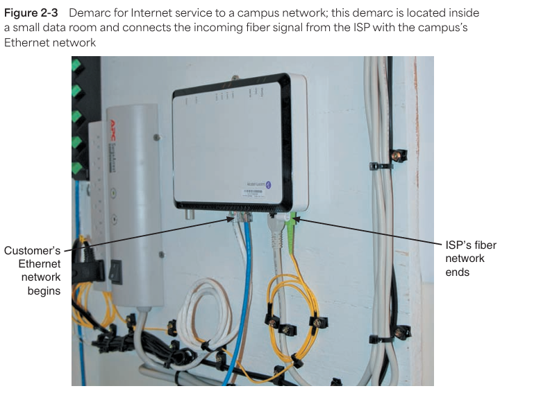
🔄 Demarc (Demarcation Point)
- Role: Exact boundary between the ISP and the customer network.
- Usually a device:
- Transceiver, media converter, or smart jack.
- Converts WAN signals to LAN-compatible signals.
- Responsibility Boundary:
- ISP → Up to the demarc.
- Organization → Beyond the demarc.
Pro Tip: The demarc point should be labeled and documented—this saves time during troubleshooting.
🧩 MDF (Main Distribution Frame)
Reflection: This is the core of the network—everything branches out from here, like the trunk of a large tree.
- Alternate Name: Equipment Room (ER).
- Central Functions:
- Hub for the LAN backbone.
- Main Cross-Connect (MC).
- Incoming connection from EF.
- Distribution to IDFs.
- Devices Found:
- Core switches, routers, firewalls.
- Network servers (file, DNS, DHCP).
- Patch panels.
- UPS/power backup.
- Fiber-optic and Ethernet cabling.
- Layout: Star Topology—MDF at the center, other devices at the ends.
Practical Tip: Focus on cooling, security, and cable management here.
🧱 Data Room (aka TR/TE)
- TR (Telecommunications Room): Larger, full room.
- TE (Telecommunications Enclosure): Smaller, closet-style.
- Purpose:
- Houses networking gear close to work areas.
- Connects back to MDF via backbone.
- Must-Have Conditions:
- Locked door for security.
- HVAC for temperature control.
- Fire-rated walls and clean cable routing.
Field Insight: Whether the room is small or large, proper airflow and access ensure network stability.
📦 Rack Systems
- Function: Structured mounting for network devices.
- Includes:
- 19” standard racks for switches, routers, servers.
- Shelves for non-rack-mountable gear.
- Benefits:
- Space optimization.
- Easy access.
- Cable management.
Observation: Neat rack = Happy tech. Messy rack = Nightmares during outages!
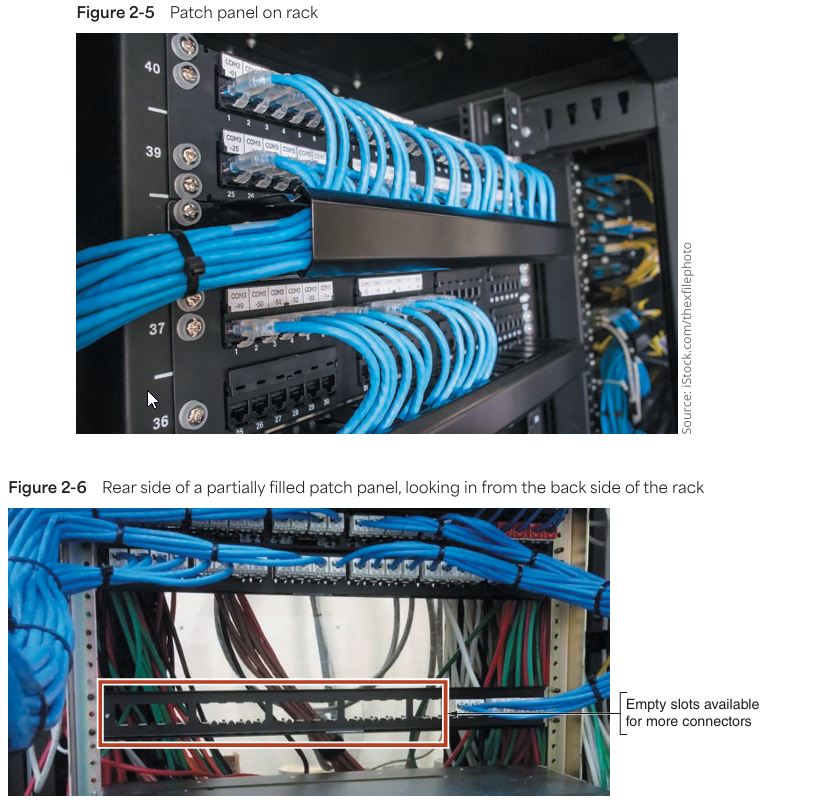
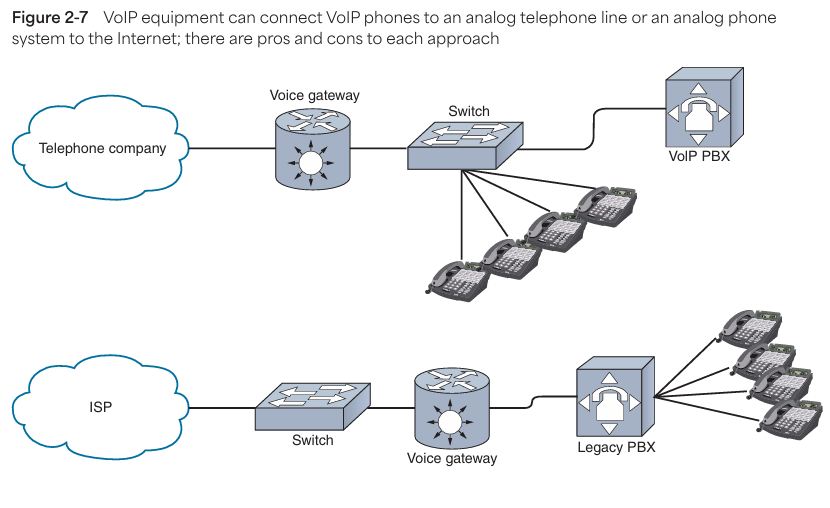
🔌 Patch Panel
- Role: Centralized cable termination point.
- Mounted: On wall or rack.
- Connections:
- Rear side → Permanent horizontal cabling.
- Front side → Patch cables to switches/routers.
Tip: Number each port and maintain a patch panel map—saves hours during audits.
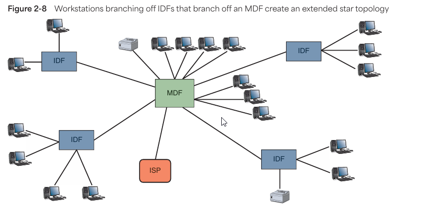
📞 VoIP Telephone Equipment
- VoIP (Voice over IP): Voice signals over data network using TCP/IP.
- Key Components:
- Voice Gateway: Converts analog ↔ IP signals.
- VoIP PBX: Internal call routing (virtual or physical).
- SIP Protocol: Starts, maintains, ends sessions.
- VoIP Phone Types:
- Desk phones.
- Softphones (apps on computer or mobile).
Reflection: A strong VoIP setup ensures smooth internal and external calling—plus lower maintenance costs.
🧭 Summary: End-to-End Network Flow
Internet → EF → Demarc → MDF → IDF → Work Area Outlet → Patch Cable → Workstation / VoIP Device
🏢 Tour Stop 2: Data Room in Building B
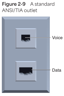
📡 IDF (Intermediate Distribution Frame)
- Role: Distributes data from the MDF to local floors or building sections.
- Location: At least 1 IDF per floor (as per ANSI/TIA standards).
- Structure:
- Can refer to the rack or full room.
- Connects to MDF via backbone cabling (fiber or high-grade Ethernet).
- Connects to workstations via horizontal cabling.
- Topology:
- Extended Star Topology.
- MDF = center star.
- IDFs = midpoints.
- Workstations = outer nodes.
- Extended Star Topology.
Pro Insight: Large organizations may have multiple IDFs per floor to optimize cable lengths and load balancing.
☎️ VoIP PBX (Private Branch Exchange)
- Function:
- IP-based telephony switch.
- Routes internal calls.
- Sends external calls via VoIP Gateway.
- Protocol: SIP (Session Initiation Protocol)—manages VoIP call sessions.
- Device Forms:
- Physical VoIP PBX box.
- Virtual/Cloud-based system.
- Connects to:
- VoIP phones (hardware or software).
- Voice gateway (for analog or PSTN interfacing).
- Network switch (for LAN traffic).
Reflection: Proper VoIP PBX integration ensures crystal-clear voice quality. This is the future!
📞 Legacy PBX (Traditional Telephony)
- Function:
- Analog/digital telephone switch.
- Connects internal extensions.
- Handles external lines via PSTN (Public Switched Telephone Network).
- Connection:
- Uses RJ-11 cabling, not IP.
- Connects to analog phones and legacy handsets.
- Why still exists?
- Some organizations haven’t fully transitioned to VoIP.
- Serves as backup or transitional infrastructure.
Note to Self: Legacy PBX maintenance and troubleshooting are different—separate cable runs, tone generators, etc.
🖥️ Tour Stop 3: Work Areas in All Three Buildings
🧩 Work Area
- Definition: Area where end-users (employees, students, customers) access the network daily.
- Devices Present:
- Workstations (desktops/laptops).
- Printers, VoIP phones.
- Barcode scanners, POS devices, etc.
- Connectivity Includes:
- Patch cables.
- Wall jacks/outlets.
- Horizontal cabling (connects to IDF).
Observation: The layout and cleanliness of the work area directly impact user satisfaction and troubleshooting efficiency.
🔌 Wall Jacks
- Placement: Mounted on walls, under desks, floor boxes.
- Standard (ANSI/TIA-568):
- Minimum 1 voice + 1 data outlet per jack.
- Variations in Real Life:
- Computer labs: Data-only, no voice.
- Meeting rooms: Multiple data jacks + HDMI + power.
- VoIP setups: One RJ45 jack for both voice & data via VLAN.
- Labeling Tip: Match jack IDs (e.g., D1-23) with IDF patch panel ports for easy tracing.
Pro Tip: Each jack should have a printed label on the wall plate—reduces confusion and downtime.
🧭 Summary Table
| Component | Description | Notes |
|---|---|---|
| Work Area | User-side network zone | End-point for device connections |
| Patch Cable | Short cable connecting device to wall jack | Generally Cat 6 or higher recommended |
| Wall Jack | RJ45 interface on wall or floor box | Labeled, minimum 1 voice + 1 data per TIA |
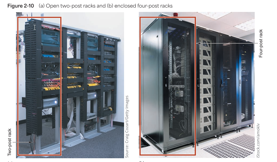
🗂️ Tour Stop: Rack Systems
🧱 Types of Rack Systems
| Rack Type | Description | Notes |
|---|---|---|
| 2-Post | Lightweight, open frame | Ideal for patch panels, light switches |
| 4-Post | Stronger, supports deeper/heavier gear | Good for servers, enclosed models available |
| 6-Post | Rare, extra support for large systems | Seen in dense enterprise setups |
- Open Frame: Easy access, good for ventilation.
- Enclosed: Physical security + dust protection.
- Mounting Options: Wall-mounted, freestanding, bolted to floor.
📏 Rack Dimensions
| Spec | Standard |
|---|---|
| Height | Measured in Rack Units (U). 1U = 1.75 inches. Standard: 42U (~6 ft) |
| Width | Industry standard: 19-inch wide. Sometimes 23-inch |
| Depth | Varies by manufacturer and equipment needs |
Tip: Use half-racks (18U–22U) where space is limited or for branch office setups.
🛠️ Rack Mounting Details
- Mounting Holes:
- Types: Round, Square (modern), Threaded.
- Square holes = tool-less, bolt-free convenience = Future ready!
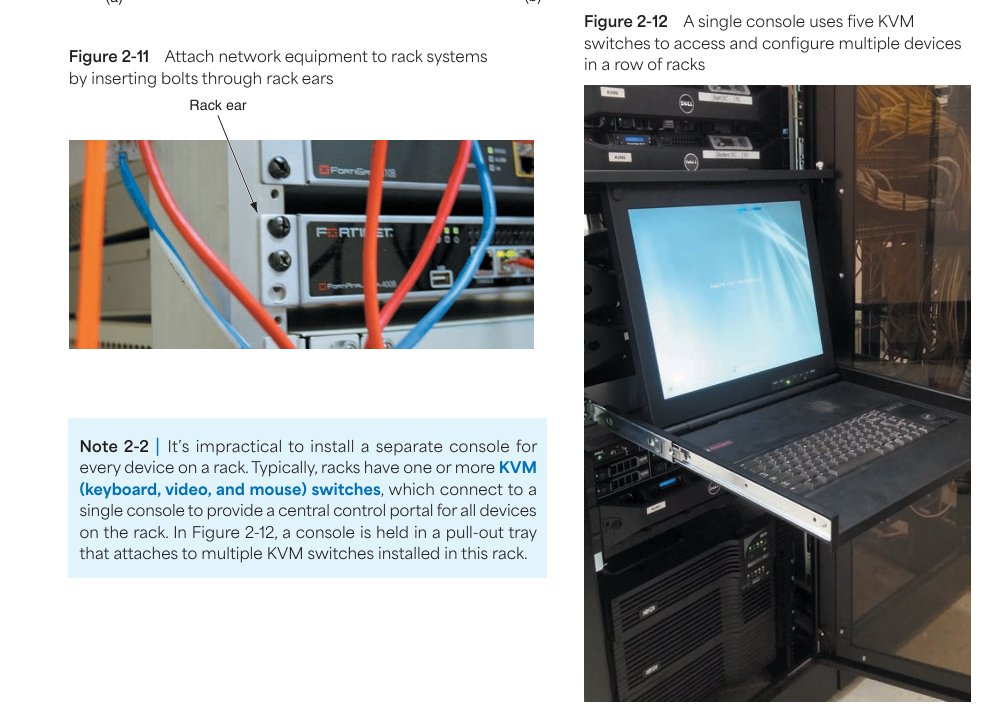
- Rack Ears: Brackets on devices that mount into rack holes.
- Add-ons:
- Power strips.
- Cooling fans.
- Cable trays.
- Slide-out drawers.
- Shelves (for non-rack-mount gear).
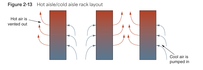
🧠 Smart Control: KVM Switches
- KVM (Keyboard, Video, Mouse) Switches
- Controls multiple servers from a single console.
- Pull-out tray-type consoles are used in racks (Figure 2-12).
- Saves time and space!
Pro Insight: Individual consoles for each device waste space. Use a KVM with a combo screen + keyboard for an optimal setup!
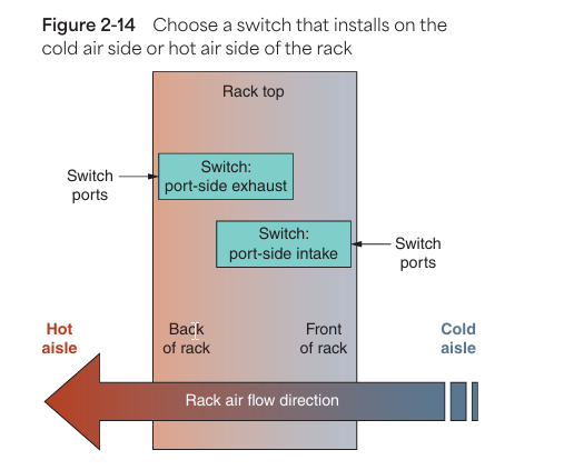
🌬️ Airflow & Cooling (Hot Aisle / Cold Aisle Concept)
| Aspect | Description |
|---|---|
| Airflow Pattern | Cold air enters from front (cold aisle), hot air exits from back (hot aisle) |
| Layout Strategy | Alternate rack rows as cold aisle / hot aisle to optimize airflow |
| Cooling Source | Raised floor vents or low wall vents push cool air in |
| Exhaust | Overhead/vented ceilings pull hot air out |
🔁 Switch Placement Strategy
| Switch Type | Faces Cold Aisle (Front) | Faces Hot Aisle (Back) |
|---|---|---|
| Port-side Intake | ✅ Yes (common setup) | ❌ No |
| Port-side Exhaust | ❌ No | ✅ Yes (less common) |
Note: Match port orientation to airflow patterns to avoid overheating!
🎯 Quick Checklist When Selecting/Installing a Rack:
✅ Rack Size matches space & device depth.
✅ Clear cable management paths.
✅ Align airflow with cooling setup.
✅ Label ports and cables.
✅ Use patch panels wherever possible.
✅ Console access via KVM.
✅ Plan for future expansion (extra RUs).
🧵 Tour Stop: Cabling
🪢 Types of Cable Installations
- 🧬 Patch Cable
- Short (3–25 feet), connectorized cable.
- Connects devices (PCs, printers) to wall jacks.
- Small but mighty!
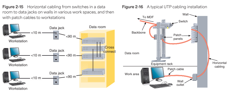
- 📐 Horizontal Cabling
- Connects workstations → IDF.
- Max length = 100 meters.
- 90m permanent link + 10m patch cables (combined).
- Uses UTP/STP/Fiber per TIA standard.
- Seen in: Data room to user outlet configurations.
- 🔗 Backbone Cabling
- Connects EF ↔ MDF ↔ IDF.
- High-capacity inter-floor/building links.
- Typically uses fiber-optic (buried, overhead, conduit enclosed).
Pro Tip: Incorrect cable installation degrades performance. Clean, labeled, and routed cables = peace of mind.
🧪 Cable Types (as per ANSI/TIA)
| Type | Details | Use Case |
|---|---|---|
| UTP | Unshielded Twisted Pair—basic, flexible, cost-effective | Standard Ethernet LAN |
| STP | Shielded Twisted Pair—extra shielding for interference protection | Industrial / high EMI zones |
| Fiber-Optic | Glass/plastic core, light signal, two types: SMF & MMF | Long-distance, backbone links |
- SMF (Single Mode Fiber): Long-range, high bandwidth (usually laser).
- MMF (Multimode Fiber): Shorter distance, cheaper (usually LED).

🧵 Tour Stop: Cable Management
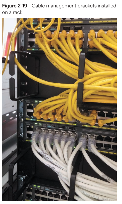
🎯 Purpose of Cable Management
- Organized layout = easy troubleshooting.
- Avoids signal interference & hardware damage.
- Prevents tripping hazards & physical wear.
- Enhances airflow = better cooling.
- Looks clean = Swag level ↑
🧰 Cable Management Tools & Techniques
| Tool / Tip | Description |
|---|---|
| Cable Ties (Velcro > Zip) | Reusable & gentle on cables |
| Cable Trays & Sleeves | Structured routing for overhead/underfloor |
| Cord Covers & Conduits | Floor protection from chairs & traffic |
| Adhesive Clips & Grommets | For discreetly mounting cables on furniture/walls |
🛡️ Installation Best Practices
- Termination:
- Stripped cable ≤ 1 inch.
- Excessive exposure = Crosstalk risk.
- Bend Radius:
- General rule: Bend ≥ 4× cable diameter.
- Overbending = signal distortion.
- Continuity Testing:
- Use a cable tester for every segment.
- Detect faults before they become outages.
- Loosely Cinched Cables:
- Tight ties = squeezed insulation = hidden signal errors.
- Loose is safer!
- Avoiding EMI:
- Keep data cables ≥ 3 ft away from motors, lights, power lines.
- Distance = Signal Clarity
🔥 Special Cases
- Plenum Cabling:
- For ceiling/subfloor installations.
- Must be flame-resistant & low-smoke.
- Always check cable jacket stamp.
- Grounding:
- Absolutely essential.
- Prevents static damage & electrical hazards.
- Cable Slack:
- Measure → remeasure → leave a little extra.
- Tight cables = high-stress & breakage risk.
🗃️ Structured Tools
- Patch Panels:
- Core of neatness—connect, organize, relabel with ease.
- Doesn’t alter signal—just routes it cleanly.
- Color Coding:
- Assign meaning to sheath color (and document it!).
- Orange = Printers.
- Green = Horizontal Cabling.
- Yellow = Backbone.
- Assign meaning to sheath color (and document it!).
- Labeling:
- Label each jack, port, and panel point.
- Makes tracing super easy.
📒 Documentation Standards
| Task | Why It Matters |
|---|---|
| Centralized doc location | Team access & updates |
| Include cable lengths/types | For planning upgrades or repairs |
| Update when changes happen | Real-time accuracy |
| Record color codes & jack IDs | Fast port identification during troubleshooting |
Pro Tip: Documentation = your future technician self’s best friend.
✅ Final Checklist: Cable Pro Swag
✔ Maintain slack.
✔ Use the right cable type (plenum, shielded, etc.).
✔ Keep EMI-safe distances.
✔ Ensure grounded setup.
✔ Use patch panels.
✔ Label everything.
✔ Update documentation.
✔ Maintain consistent color coding.
✔ Avoid crushing or pinching cables.
Monitoring the Environment and Security
1. Importance of Environmental Monitoring
- Sensitive Equipment & Monitoring: Equipment mounted on racks, such as servers and switches, is highly sensitive and requires environmental and security monitoring.
- Temperature Sensors: Servers and switches have in-built temperature sensors. If the device temperature rises, technicians receive alerts.
- HVAC System: Data rooms have HVAC systems to maintain temperature, ensuring sensitive servers stay cool and performance isn’t impacted. These systems are managed separately from the rest of the building.
2. Specialized Environmental Monitoring Products
- Vertiv Products: Vertiv provides environmental monitoring products that track temperature, humidity, and airflow. If unacceptable conditions arise, alerts (email/text) are sent.
- Security Alerts: Alerts are also triggered for open secure doors, power supply issues, or light/sound anomalies.
- Networked HVAC Sensors: HVAC systems and sensors are networked devices operating under an ICS (Industrial Control System). ICS collects real-time data and presents it for monitoring.
3. ICS and SCADA
- ICS (Industrial Control System): Monitors and controls physical systems. Handles HVAC, lighting, power supply, water treatment, and other environmental factors.
- SCADA (Supervisory Control and Data Acquisition): An advanced version of ICS, monitoring wide-scale control systems. Examples include city-wide HVAC systems or electric utilities.
- OT (Operational Technology): Sensors, controls, and computing systems that directly monitor and control physical infrastructure. OT is used in diverse industries like manufacturing, mining, and fuel monitoring.
- Security for SCADA/OT Systems: These systems are on separate network segments, isolated from sensitive data and internet access for security.
4. Environmental Alarms & Alerts
- Programmed Alarms: Environmental monitoring systems can be programmed to escalate alerts to higher-level staff as problem severity increases.
- Example: Rising humidity indicates increased moisture in the air, which can damage sensitive equipment. If the source is a leak, it could also pose a safety hazard.
- Data Recording & Pattern Analysis: Monitoring systems record data, allowing technicians to analyze fluctuations and patterns for timely action.
5. Security in Data Rooms
- Locked Doors: Data rooms should have locked doors, with access limited to IT staff (keys/entrance codes).
- Security Cameras: Install security cameras at access points to monitor tampering or break-ins. These cameras are usually on separate, secure network segments.
6. Campus Network Tour Recap
- Internet Connection Flow: Internet connection enters the premises at the demarcation point, reaches the MDF, and is distributed to campus IDFs.
- Cable Types & Installation: Proper planning of cables and installations is crucial for efficient network functioning.
- Documentation: IT staff must track network equipment, software configurations, and vendor information. Documentation is vital when working on the network.
7. Conclusion & Key Takeaways
- Environmental & Security Monitoring: Both aspects are critical. Efficient monitoring systems (HVAC, Vertiv, ICS, SCADA) protect data rooms and sensitive equipment.
- Documentation: Accurately maintaining and updating network configurations, equipment, and vendor information is invaluable for the future.